- 您现在的位置:买卖IC网 > Sheet目录509 > SI4355-B1A-FM (Silicon Laboratories Inc)IC EZRADIO FM RECEIVER SI4355
�� �
�
�Si4355�
�5.4.� Interrupts�
�The� Si4355� is� capable� of� generating� an� interrupt� signal� when� certain� events� occur.� The� chip� notifies� the�
�microcontroller� that� an� interrupt� event� has� occurred� by� setting� the� nIRQ� output� pin� LOW� =� 0.� This� interrupt� signal�
�will� be� generated� when� any� one� (or� more)� of� the� interrupt� events� occur.� The� nIRQ� pin� will� remain� low� until� the�
�microcontroller� reads� the� Interrupt� Status� Registers.� The� nIRQ� output� signal� will� then� be� reset� until� the� next� change�
�in� status� is� detected.�
�The� interrupt� sources� are� grouped� into� three� categories:� packet� handler,� chip� status,� and� modem.� The� individual�
�interrupts� in� these� groups� can� be� enabled/disabled� in� the� interrupt� property� registers,� 0x0101,� 0x0102,� and� 0x0103.�
�An� interrupt� must� be� enabled� for� it� to� trigger� an� event� on� the� nIRQ� pin.� The� interrupt� group� must� be� enabled� as� well�
�as� the� individual� interrupts� in� API� property� 0x0100.�
�Once� an� interrupt� event� occurs� and� the� nIRQ� pin� is� low� the� interrupts� are� read� and� cleared� using� the�
�GET_INT_STATUS� command.� By� default� all� interrupts� will� be� cleared� once� read.� The� instantaneous� status� of� a�
�specific� function� may� be� read� if� the� specific� interrupt� is� enabled� or� disabled.� The� status� results� are� provided� after�
�the� interrupts� and� can� be� read� with� the� same� commands� as� the� interrupts.� The� status� bits� will� give� the� current� state�
�of� the� function� whether� the� interrupt� is� enabled� or� not.�
�5.5.� GPIO�
�Four� General� Purpose� IO� (GPIO)� pins� are� available� for� use� in� the� application.� The� GPIOs� are� configured� using� the�
�GPIO_PIN_CFG� command.� GPIO� pins� 0� and� 1� should� be� used� for� active� signals� such� as� data� or� clock.� GPIO� pins�
�2� and� 3� have� more� susceptibility� to� generating� spurious� components� in� the� synthesizer� than� pins� 0� and� 1.� The� drive�
�strength� of� the� GPIOs� can� be� adjusted� with� the� GEN_CONFIG� parameter� in� the� GPIO_PIN_CFG� command.� By�
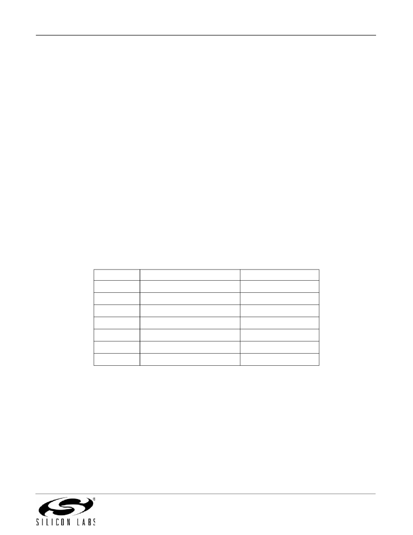
�default,� the� drive� strength� is� set� to� the� minimum.� The� default� configuration� and� the� state� of� the� GPIO� during�
�shutdown� are� shown� in� Table� 14.� For� a� complete� list� of� the� GPIO� options,� please� refer� to� the� API� guide� application�
�note,� “AN691:� EZRadio� API� Guide”.�
�Table� 14.� GPIOs�
�Pin�
�GPIO0�
�GPIO1�
�GPIO2�
�GPIO3�
�nIRQ�
�SDO�
�SDI�
�SDN� State�
�0�
�0�
�0�
�0�
�Resistive� V� DD� pull-up�
�Resistive� V� DD� pull-up�
�High� Z�
�Rev� 1.0�
�POR� Default�
�POR�
�CTS�
�POR�
�POR�
�nIRQ�
�SDO�
�SDI�
�25�
�发布紧急采购,3分钟左右您将得到回复。
相关PDF资料
SI4388DY-T1-GE3
MOSFET DUAL N-CH 30V 8-SOIC
SI4390DY-T1-GE3
MOSFET N-CH 30V 8.5A 8SOIC
SI4396DY-T1-GE3
MOSFET N-CH D-S 30V 8-SOIC
SI4398DY-T1-GE3
MOSFET N-CH 20V 19A 8-SOIC
SI4404DY-T1-GE3
MOSFET N-CH D-S 30V 8-SOIC
SI4406DY-T1-GE3
MOSFET N-CH D-S 30V 8-SOIC
SI4410DY
MOSFET N-CH 30V 10A 8-SOIC
SI4411DY-T1-GE3
MOSFET P-CH D-S 30V 8-SOIC
相关代理商/技术参数
Si4355-B1A-FMR
功能描述:射频接收器 Si4355 EZRadio Rcvr
RoHS:否 制造商:Skyworks Solutions, Inc. 类型:GPS Receiver 封装 / 箱体:QFN-24 工作频率:4.092 MHz 工作电源电压:3.3 V 封装:Reel
SI4355-B1A-GM
制造商:Silicon Laboratories Inc 功能描述:SI4355 EZRADIO RECEIVER - Bulk
SI4356ADY
制造商:VAISH 制造商全称:VAISH 功能描述:N-Channel 30-V (D-S) MOSFET
Si4356ADY-T1-E3
功能描述:MOSFET 30V 26A 6.5W RoHS:否 制造商:STMicroelectronics 晶体管极性:N-Channel 汲极/源极击穿电压:650 V 闸/源击穿电压:25 V 漏极连续电流:130 A 电阻汲极/源极 RDS(导通):0.014 Ohms 配置:Single 最大工作温度: 安装风格:Through Hole 封装 / 箱体:Max247 封装:Tube
SI4356ADY-T1-GE3
功能描述:MOSFET 30V 26A 6.5W 5.5mohm @ 10V RoHS:否 制造商:STMicroelectronics 晶体管极性:N-Channel 汲极/源极击穿电压:650 V 闸/源击穿电压:25 V 漏极连续电流:130 A 电阻汲极/源极 RDS(导通):0.014 Ohms 配置:Single 最大工作温度: 安装风格:Through Hole 封装 / 箱体:Max247 封装:Tube
SI4356-B1A-FM
制造商:Silicon Laboratories Inc 功能描述:SI4356 STANDALONE SUB-GHZ RECE 制造商:Silicon Laboratories Inc 功能描述:SI4356 STANDALONE SUB-GHZ RECEIVER - Rail/Tube 制造商:Silicon Laboratories Inc 功能描述:IC RX SUB-GHZ STAND ALONE QFN 制造商:Silicon Laboratories Inc 功能描述:RF Receiver Si4356 Standalone Sub-GHz Receiver
SI4356-B1A-FMR
制造商:Silicon Laboratories Inc 功能描述:SI4356 STANDALONE SUB-GHZ RECE 制造商:Silicon Laboratories Inc 功能描述:RECEIVER RF CI SMD - Tape and Reel 制造商:Silicon Laboratories Inc 功能描述:RF Receiver Si4356 Standalone Sub-GHz Receiver
SI4356DY
制造商:VISHAY 制造商全称:Vishay Siliconix 功能描述:N-Channel 30-V MOSFET